TRÅDFRI wall switch: Forskelle mellem versioner
Pmr (diskussion | bidrag) |
Pmr (diskussion | bidrag) |
||
| Linje 125: | Linje 125: | ||
| 200 || S5 || [[Fil:PTS641SM34SMTR2LFS.png|40px]]<br>[[Fil:PTS641SP34SMTR2LFS.png|40px]] || 135-9404<br>N/A || N/A<br>CKN10814CT-ND || N/A<br>N/A || N/A<br>611-641SP34SMTR2LFS || C & K<br>C & K || PTS641 SM34 SMTR2 LFS<br>PTS641 SP34 SMTR2 LFS | | 200 || S5 || [[Fil:PTS641SM34SMTR2LFS.png|40px]]<br>[[Fil:PTS641SP34SMTR2LFS.png|40px]] || 135-9404<br>N/A || N/A<br>CKN10814CT-ND || N/A<br>N/A || N/A<br>611-641SP34SMTR2LFS || C & K<br>C & K || PTS641 SM34 SMTR2 LFS<br>PTS641 SP34 SMTR2 LFS | ||
|- | |- | ||
| 200 || S6 || [[Fil:JS203011SCQN.png|40px]]<br>[[Fil:JS203011CQN.png|40px]]<br>N/A || 154-2583<br>154-6145<br>N/A || CKN10849CT-ND<br>401-2004-ND<br>N/A || N/A<br>2435144<br>N/A || 611-JS203011SCQN<br>611-JS203011CQN<br>N/A || C & K<br>C & K<br>N/A || JS203011SCQN<br>JS203011CQN<br>MSS23D19 | | 200 || S6 || [[Fil:JS203011SCQN.png|40px]]<br>[[Fil:JS203011CQN.png|40px]]<br>N/A || 154-2583<br>154-6145<br>N/A<br>N/A || CKN10849CT-ND<br>401-2004-ND<br>N/A<br>N/A || N/A<br>2435144<br>N/A<br>N/A || 611-JS203011SCQN<br>611-JS203011CQN<br>N/A<br>N/A || C & K<br>C & K<br>N/A<br>N/A || JS203011SCQN<br>JS203011CQN<br>MSS23D19<br>MSS-23D19G2-T | ||
|- | |- | ||
| 1000 || C1-5 || || 135-9020 || || || || || | | 1000 || C1-5 || || 135-9020 || || || || || | ||
Versionen fra 24. feb. 2020, 18:11
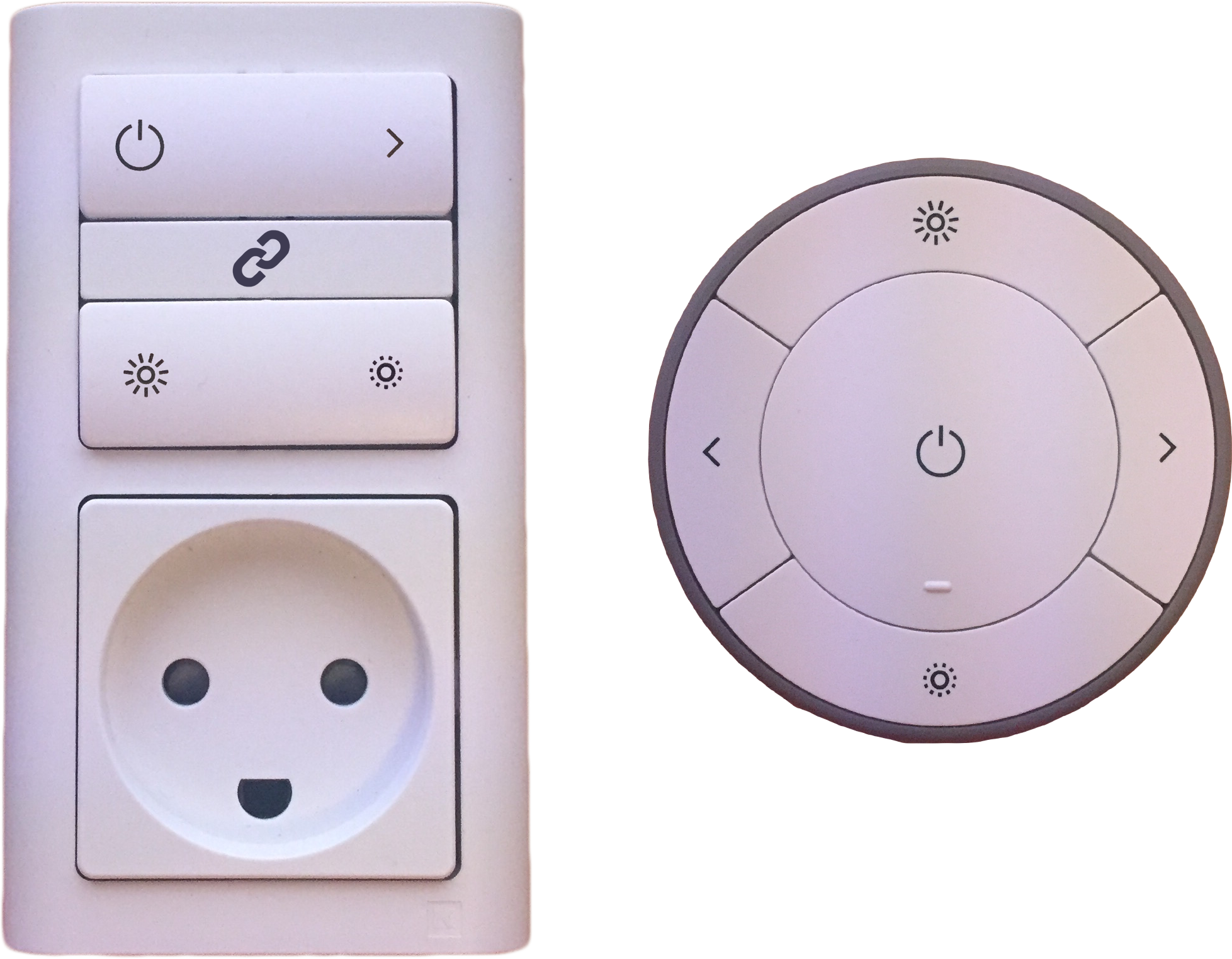
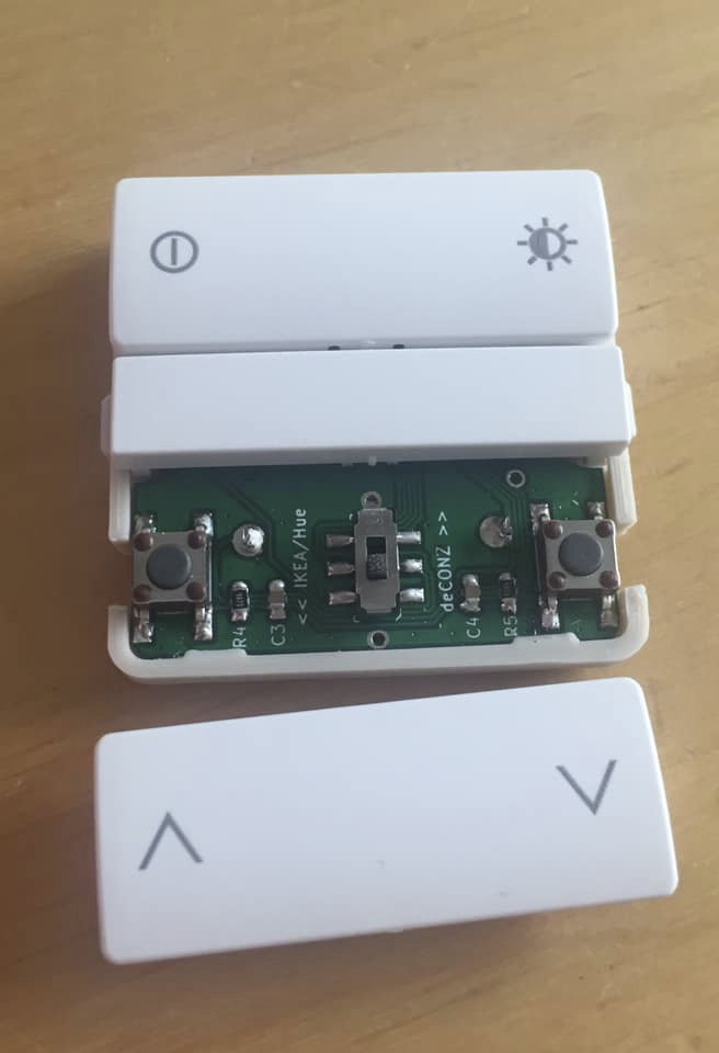
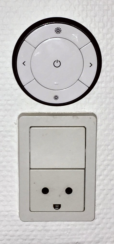
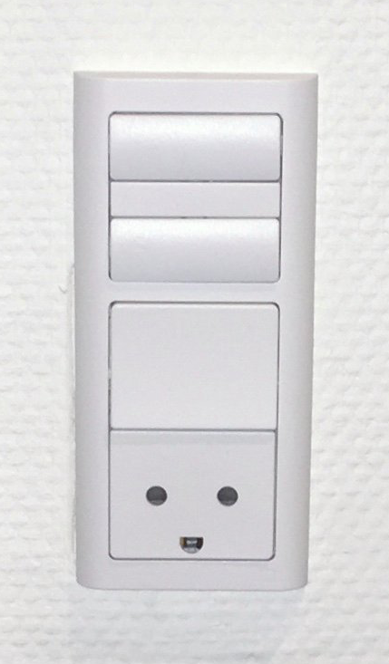
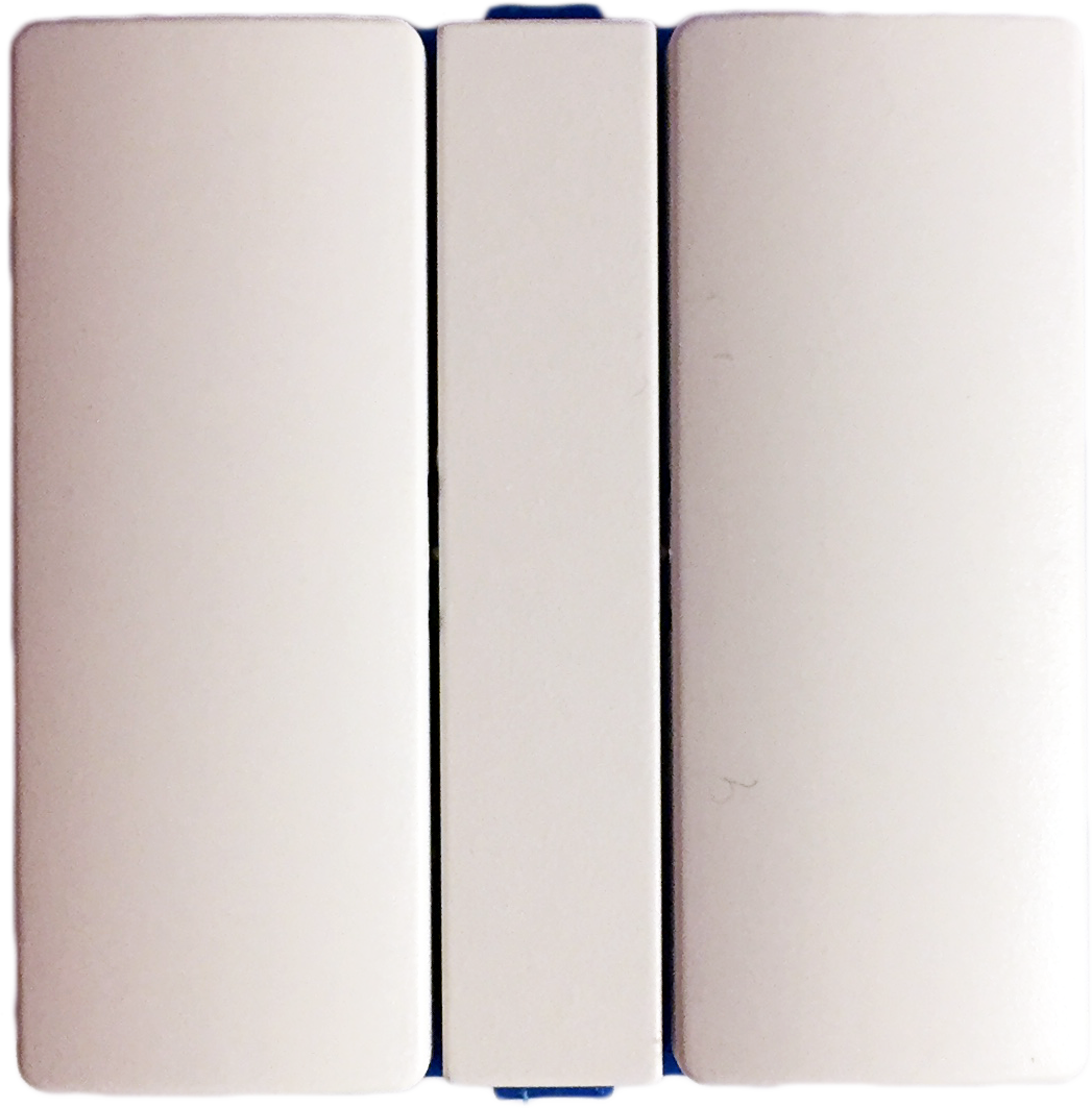
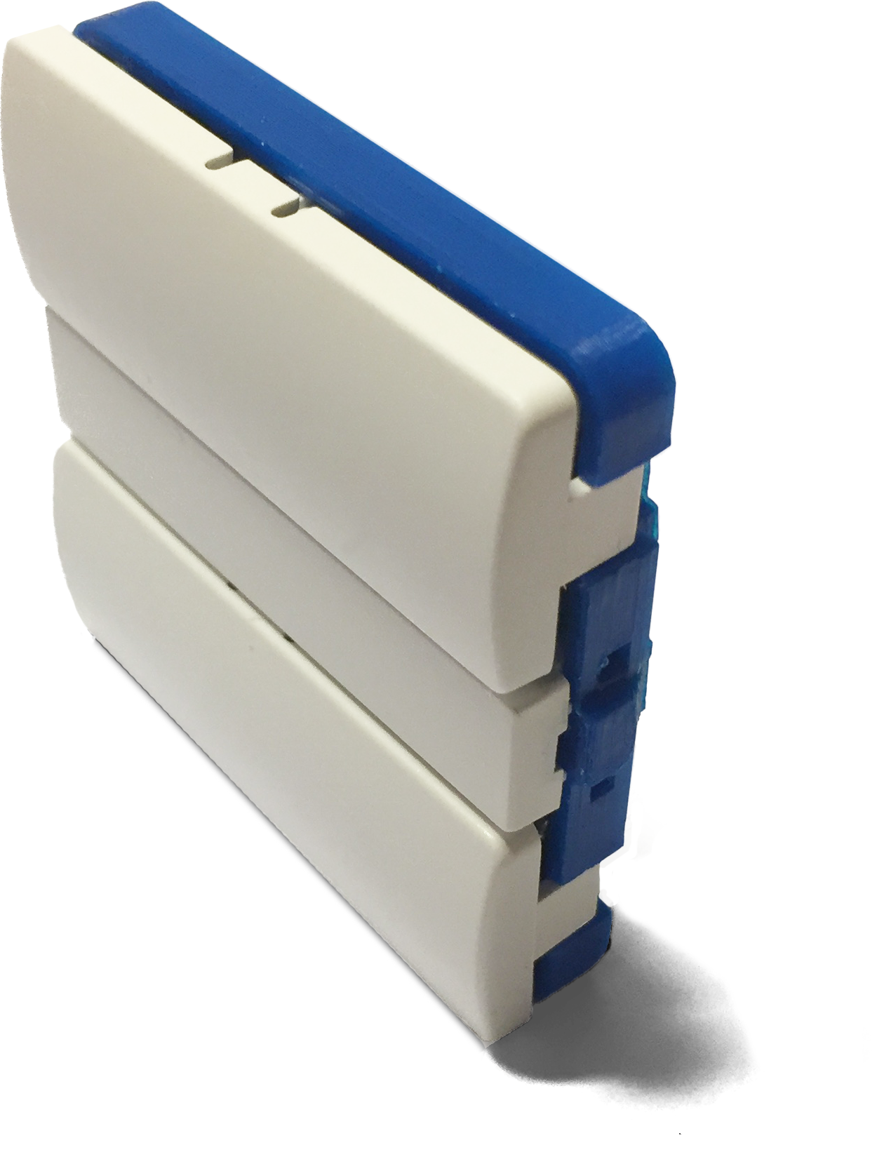
This hack will modify the TRÅDFRI remote into an attractive wall switch.
The project homepage (in Danish): https://www.thingiverse.com/thing:3655354
This information is under CC BY-NC-SA 4.0 license.
Photos
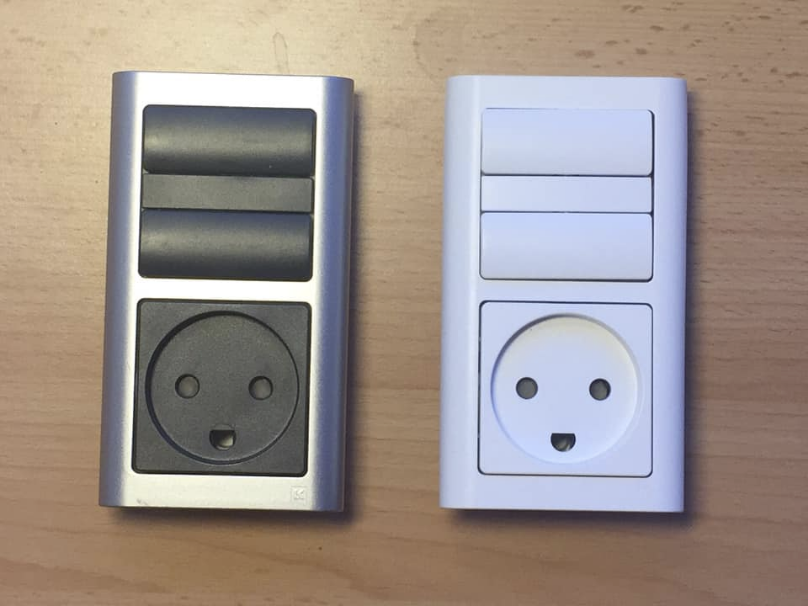
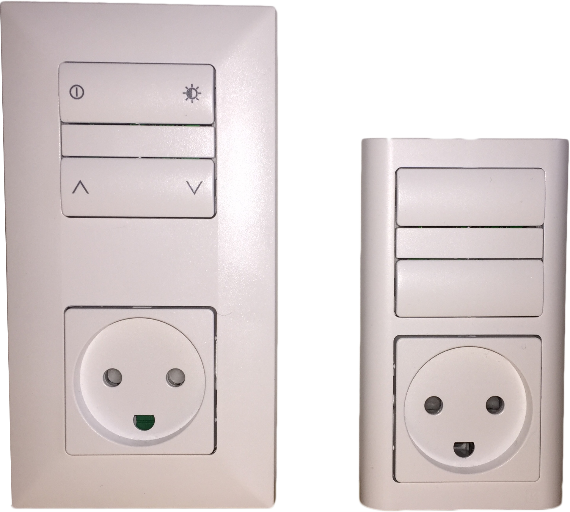
63 mm wide. Typical color choices are white or dark gray - silver combo.
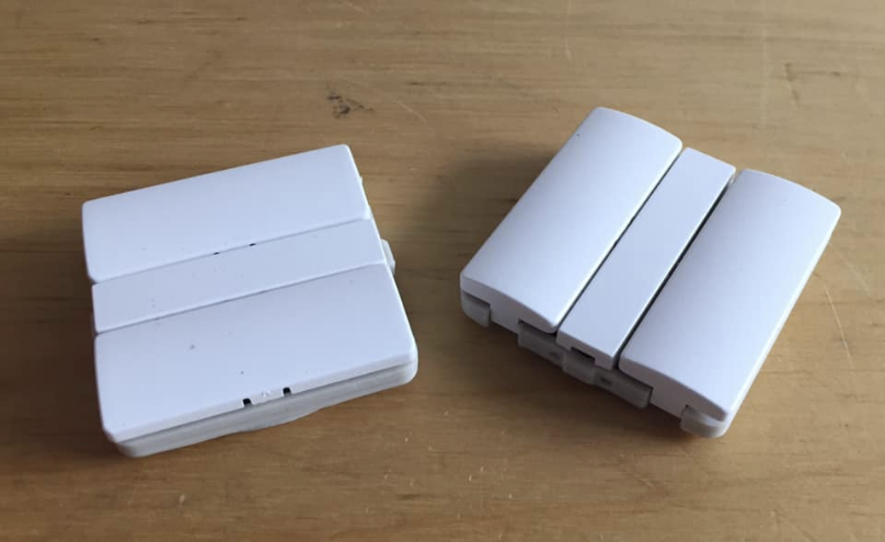
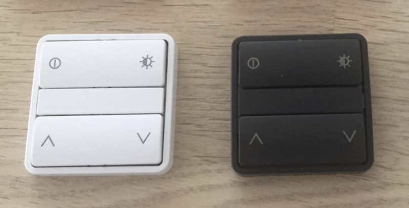
The switch are 45 x 45 x 12 mm, and does not require room behind it.
With a smaller bezel the switch can be 50 mm wide.
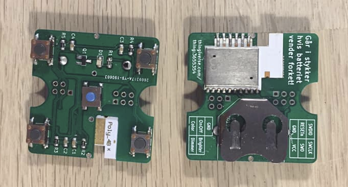
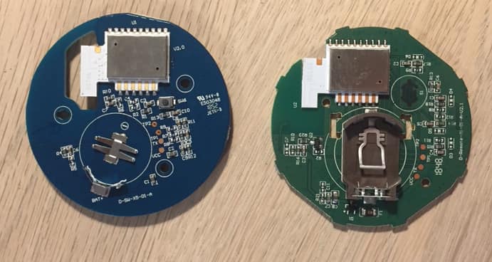
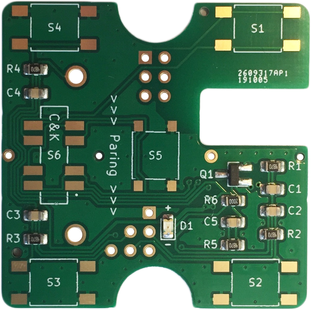
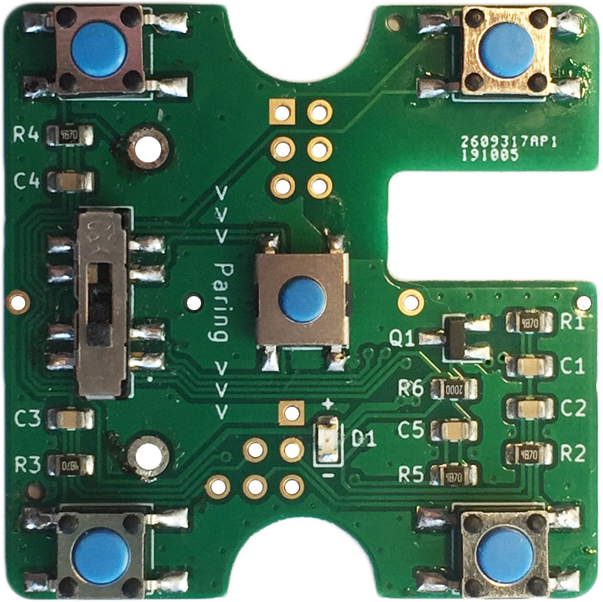
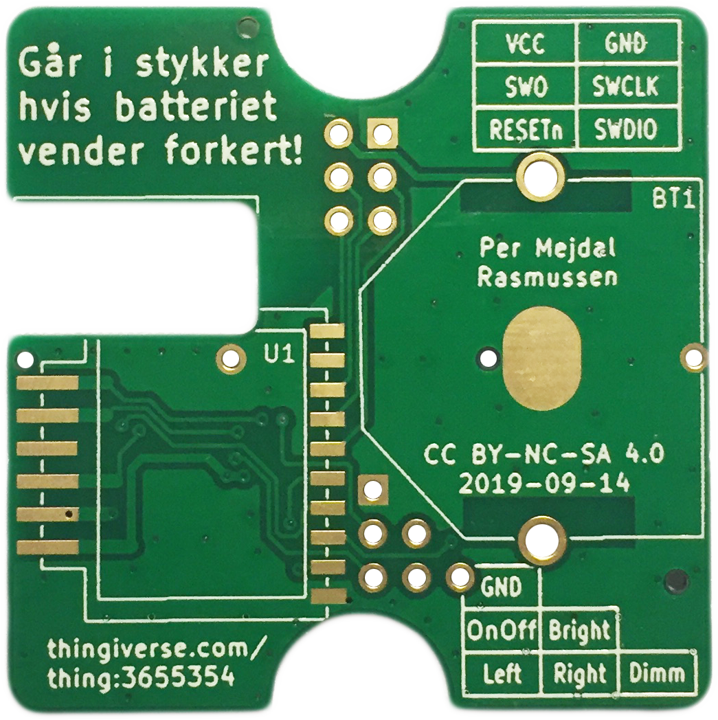
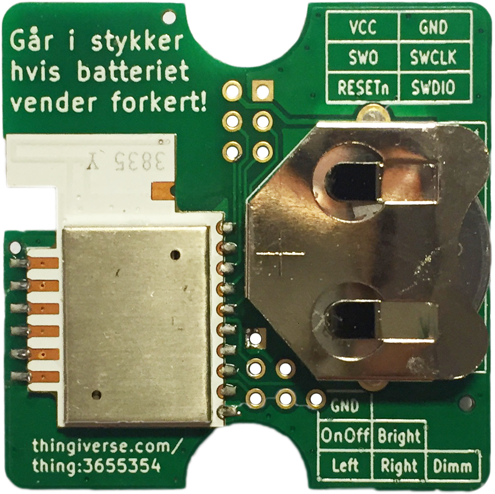
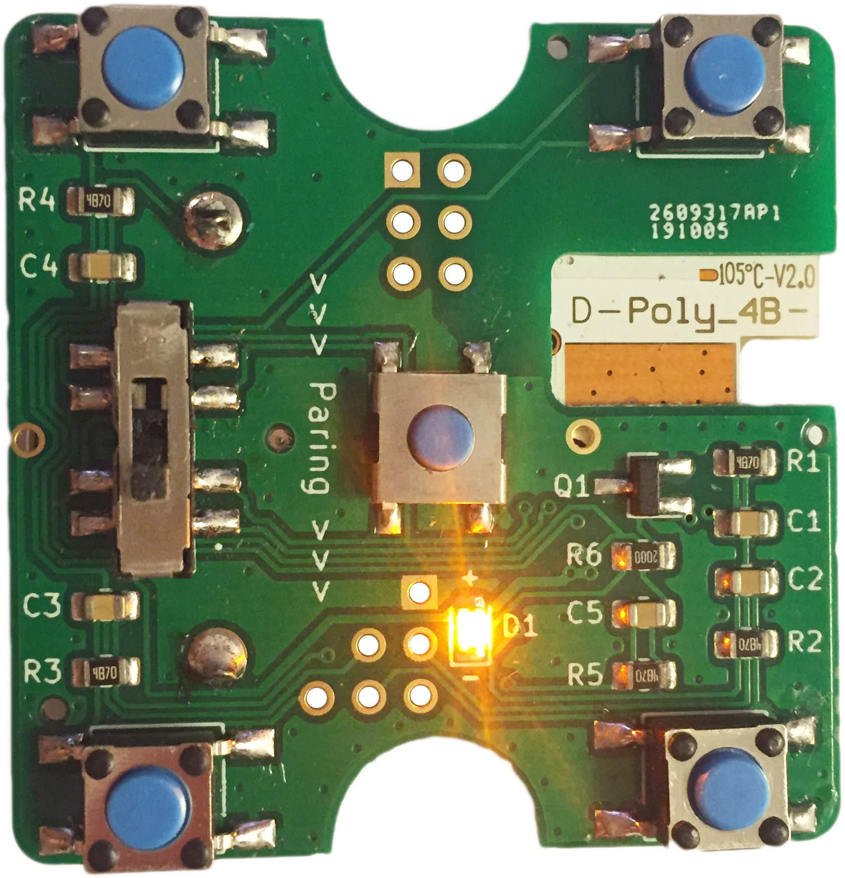
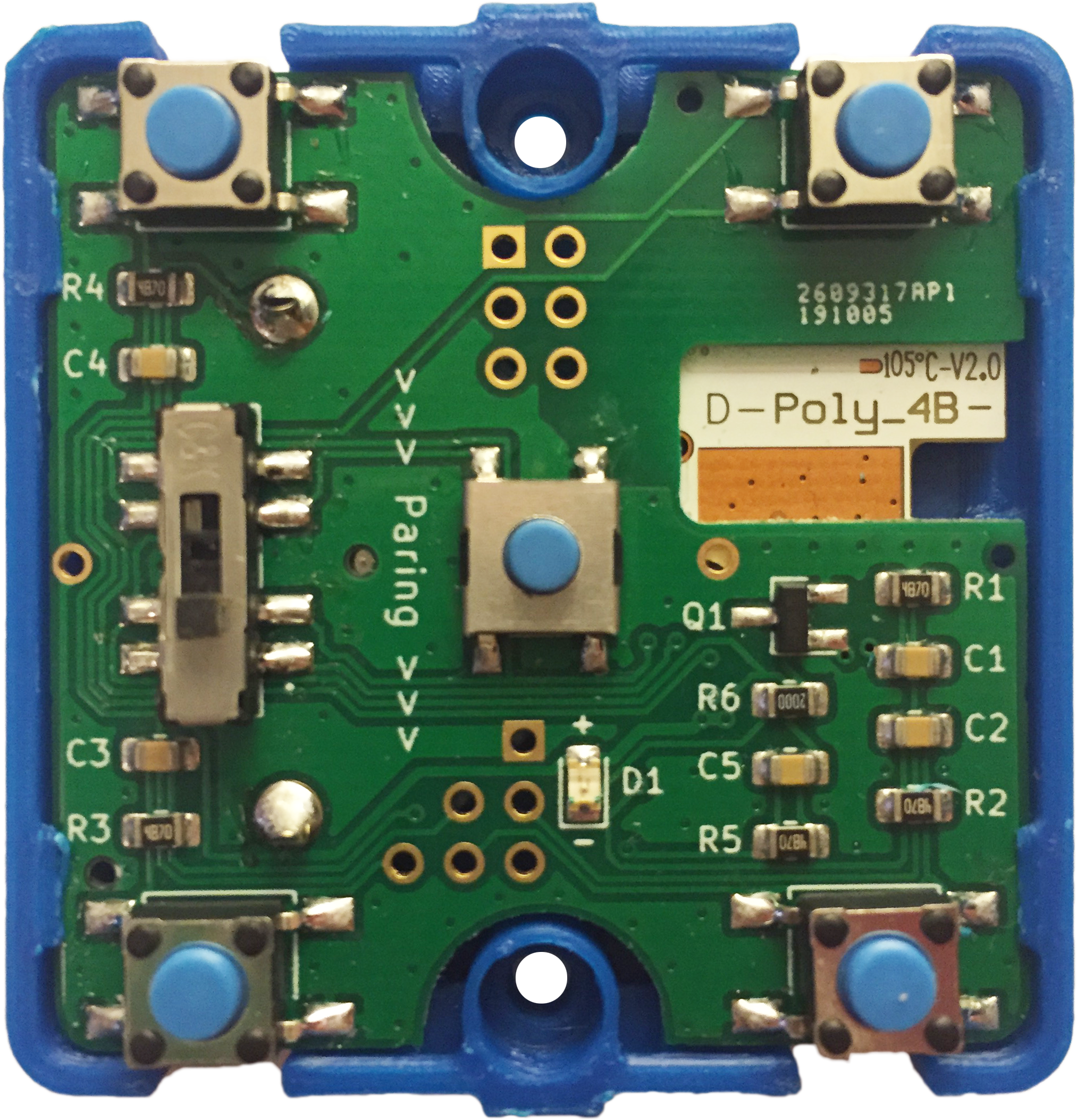
Both sides of the custom circuit board.
Custom print on plastic is possible.
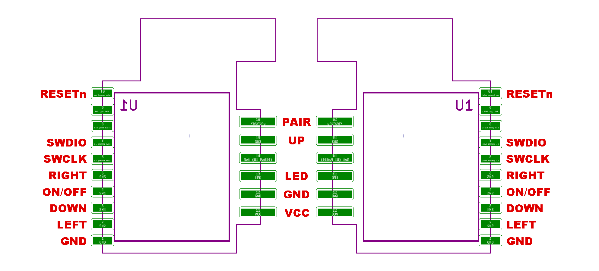
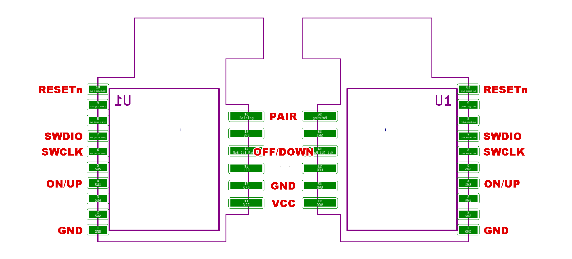
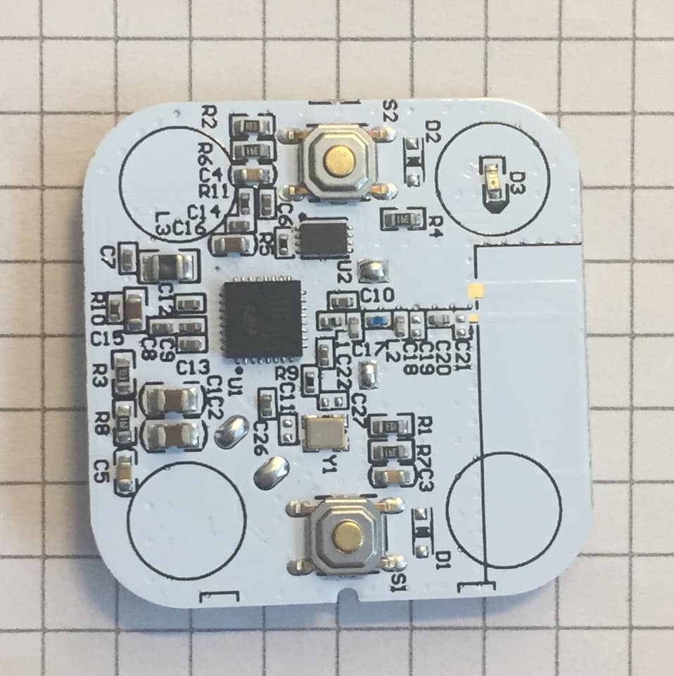
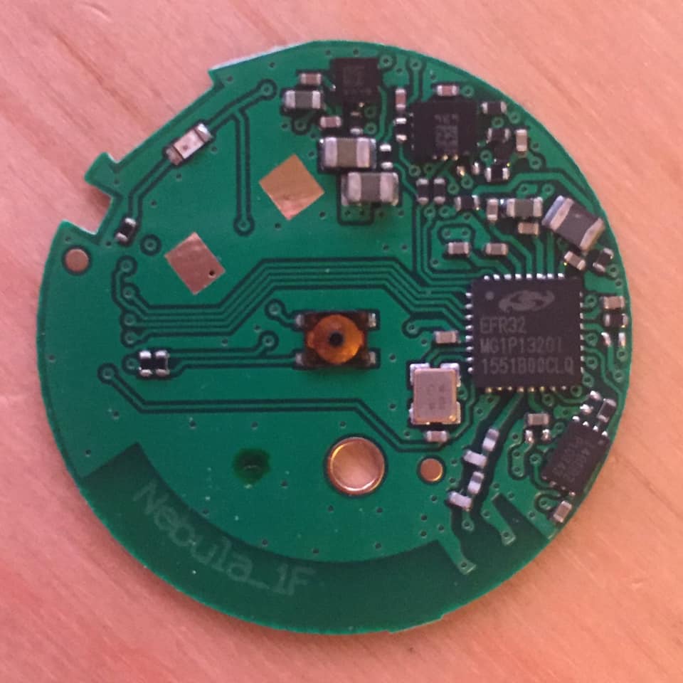
The ZigBee module from IKEA can have different functions, depending which firmware is installed.
But why?
Problem, step 1
Using TRÅDFRI on a sofa lamp is great. You can turn it on and off from your phone, and you can place a remote switch where you like.
However when you start using TRÅDFRI to replace existing ceiling lighting, you will soon realize a problem: If the light is turned off by the wall switch, you cannot turn it on by remote or app, because there is no power going to the light.
Solution, step 1
Replace the wall switch with a remote.
Problem, step 2
This looks unattractive, and does not fit into the existing wall switch and socket design.
Solution, step 2
Transfer the electronics from the remote to a switch that fits the design. The the design is so compact, that is does not requires space behind it, and can be mounted directly on the wall.
Problem, step 3
This design is for the FUGA system, which is only used in Denmark.
Solution, step 3
You can use converters to make it converter to fit the size used in the rest of Europe.
Problem, step 4
This does not look as attractive.
Solution, step 4
Be inspired by this hack, to make a solution that fits your wall switch and plug system. Be careful with mains electricity, an the note of the the law and regulations in your country. This hack avoids mains electricity by being mounted directly on the wall.
Building instructions
This guide is for at batch of 200 units. If you want a smaller amount like 20, you can order circuit boards without components, and order all the components at RS Components. However it is much easier and cost effective to follow the guide and make 200 units.
Materials needed
- ZigBee module from IKEA TRÅDFRI remote control
- Plastic for LK FUGA svagstrømstryk
- Circuit board and components
- 3D printed plastic for the back
Order circuit board with components
- Download svagstromstryk_PCB_2019-09-14_4xPannel.zip
- Extract IKEA_Button2_BOM_JLCPCB.xlsx and IKEA_Button2-top-pos_JLCPCB.xlsx from it.
- Go the the web page https://jlcpcb.com/
- Click "QUOTE NOW".
- Upload svagstromstryk_PCB_2019-09-10_4xPannel.zip.
- Set "PCB Qty" to 50.
- Set "Surface Finish" to ENIG-RoHS (not required, if you want to save cost at the expense of the environment).
- Change thickness til 1.0 mm.
- Enable "SMT Assembly" -> "Assemble your PCB boards".
- Pick "Assemble top side".
- Click "Confirm".
- Upload IKEA_Button2_BOM_JLCPCB.xlsx as BOM file.
- Upload IKEA_Button2-top-pos_JLCPCB.xlsx as CPL file.
- Click "NEXT".
- Review and confirm all the components.
- Click "NEXT".
- Review Parts Placement.
- Click "SAVE TO CART"
- Continue the Checkout. DHL is faster for delivery.
Order additional electronic components
Most components are included on the board if you buy them mounted from JLCPCB. The rest can be bought from the resellers below.
When there are multiple choosies for components, the top one is the recommended. If JS203011SCQN is sold out, JS203011CQN can be used as an alternative. You must convert it from thou-hole to SMD, by bending the legs.
In this example I bought:
- RS Components
- 200 x 135-9404
- DigiKey
- 1000 x CKN9112TR-ND (only 800 is needed)
- 200 x CKN10849CT-ND
- 200 x BK-888-ND
Order original LK FUGA plastic front
The plastic can purchased by these EAN numbers:
| Color | Buttons | Center |
|---|---|---|
| White | 5703302140836 | 5703302132244 |
| Light gray | 5703302140829 | 5703302132237 |
| Dark gray | 5703302140843 | 5703302132251 |
You need 400 buttons and 200 center plastic.
If you want laser engraved buttons, they can be ordered at bestil.lk.dk.
Remember to choose "IHC svagstrømstryk", not "IHC wireless". They look similar, but are not compatible.
Print the back side
Download the appropriate model
- With support: svagstromstryk_lukket-bagside_med-support.stl
- Without support: svagstromstryk_lukket-bagside_uden-support.stl
Tolerances are very small. The space inside must be 41.6 mm wide. Depending you the type of plastic used, the model must be enlarged between 100.2 and 100.8%. The "ironing" feature in Cura is also very useful, because it make assembling easier. Remember to pass this info along, if someone else print the model for you. Teste one, before you print a lot.
Extract the TRÅDFRI ZigBee module
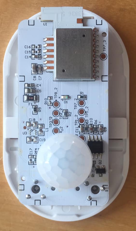
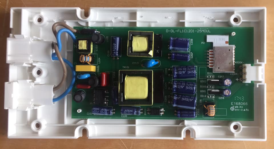
The ZigBee module is inside the TRÅDFRI remote. It can be purchased directly by the number 304.431.24. It is also included in a variety of bundles.
The extraction of the module is quite hard, and the remote is fairly expensive in some regions. Alternatively you can to use the ZigBee module from other TRÅDFRI devices, if you reprogram it.
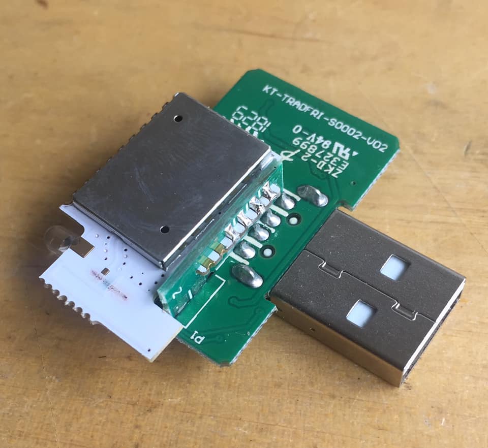
The TRÅDFRI signal repeater is the easiest product to extract the module from. Just push on the USB plug, and it pops open. It is only soldered on 4 pads.
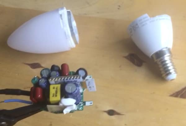
The bulbs are harder to open, but are easy to desolder, because it is only soldered on one side. The 400 lm white bulb is the cheapest option to the the module.
Most TRÅDFRI products has the ZigBee module. You can recycle broken or unused devices.
Except the ON/OFF remote and the dimmer remote, they don't have the module.
Assembly
Solder the components on the circuit board in this order:
Top side: Small components (already done if ordered with components on).
Top side: Switches and buttons.
Back side: ZigBee module.
Back side: Battery holder (remember to fill the center pad with solder).
If you used an alternative ZigBee module, you must reprogram it now
Insert battery, note the polarity. There is a plus sign on both the battery holder and the battery, they should match.
After clicking 4 times on pairing button, The LED should start flashing.
Inset the circuit board into the plastic back. Mount the battery side first. It might be necessary to remove some plastic under the tabs.
Mount the frost side plastic.
Test that everything is working. Enjoy!
